INSTRUCTIONS FOR ASSEMBLING MOTOR DRIVE KIT WITH TYPE II MANUAL SWAGING MACHINE – M2-PDK
Refer to the part list for the location of the swaging machine parts mentioned below.
- Take out capscrew -1 and washer -9 to remove operating lever from square drive lug of crankshaft -36.
- Take out screws -26 and -27 and remove gear guard -28.
- Remove internal reversing latch, which consists of the following parts:-29 Lift Pin, Reverse Latch
-46 Spring Latch
-47 Adapter, Latch Spring
-48 Hex Jam Nut 3/8 x 3/16
-49 Collar, Latch Spacer
-50 Bolt, Latch
-51 Latch, Reverse
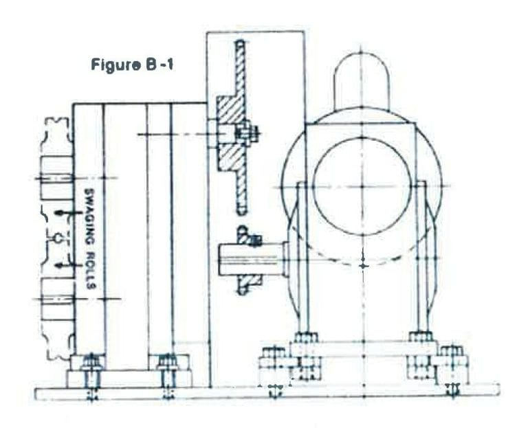
(Note do not replace gear guard) - The drive motor and reduction gear, already assembled are shipped mounted on a 12″ x 17 1/2″ x 1/2″ Steel base plate, shown in Figure B-1.This plate is predrilled with the four mounting bolt holes for the Type II Swaging Machine.
Place the Swaging Machine on the base plate and using 3/8 x 1 1.4″ allen head bolts with flat washers secure the machine and the base plate to the bench.
- Slide the smaller sprocket onto the output shaft of the speed reducer, but do not secure it.
- Engage the roller chain with the two sprockets and then engage the larger sprocket with the square drive lug of the swaging machine. Secure it with capscrew -1 and flat washer -9.
- Slide the smaller sprocket in or out on the output shaft of the speed reducer to align it with the larger sprocket and then secure it with the setscrew in its hub.
- Adjust the spacing of the two sprockets to obtain proper chain tension. The chain can be tightened by transferring the flat washers on the mounting bolts of the reducer gear housing from the underside of the housing to the upper side. Transferring rather than simply removing the flat washers avoids the necessity of changing to a shorter mounting bolt. Be sure to transfer the same number of washers on each of the four mounting bolts.A final fine adjustment can be obtained by loosening the mounting bolts of the Swaging Machine and sliding it on the base plate in the appropriate direction as permitted by its slotted mounting holes. The chain is properly tensioned when its slack permits a total crossways movement of the chain of 1/4″.
- Install the Chain Guard between the motor drive unit and the swaging machine and secure it to the base plate with two hex head machine screws engaging tapped holes provided in the base plate.
- Plug the electrical cord into a suitable electrical power supply (110 volt).