Specifications
Kit Contains:
A) 12×19 Mounting Plate
B) Adjustable Base to Tighten Chain
C) Right Angle Gear Reducer including 1-1/2″ HP Single Phase 115 volt motor.
D) Foot Switch with 5 feet of cord connected to motor and 10 feet of cord for connection to power supply.
E) 2 Chain Sprockets and Roller Chain
E) Necessary cap screws to mount gear box, swager and guard.
F) Chain Guard
Precaution
When swaging fittings on to 1 x 19 construction wire rope, remember that there is little or no compression remaining in this construction. The wire rope itself is very solid with little or no “give.”
A combination of a 1 x 19 construction wire rope manufactured on the “high side” of its tolerance and a fitting with a hole running on the “low side” of its tolerance (see dimensions to fittings under specifications) will exaggerate this problem. Remember a swaging machine must have room to “flow” or “move” the steel in the fitting to form around the wire rope. There must be space to accomplish this.
In addition, many manufacturers do not drill the hole in their fittings deep enough. This leaves a space at the base of the fitting of solid steel. This distance can vary from 1/4″ up to over 1″. The Locoloc® Kearney machine simply cannot perform the impossible and swage solid metal, again there must be room for the steel to “flow” or “move.”
When any of the situations above occur, the result can only be broken dies, sprung machines, ruined fittings and perhaps loss of expensive wire rope. The majority of cases could easily be avoided by checking the following before attempting to swage:
- Diameter of wire rope – is it on high side of tolerance?
- Inside diameter of fitting – will the wire rope fit with ease?
- Depth of hole in fitting – do not attempt to swage over solid steel, begin swage at the bottom of the hole.
- Hardness of steel – check Rockwell Hardness. See above.
- Do not add leverage to your swaging machine by extending the handle beyond the length of the handle extension we supply. The handle is designed to accomplish the maximum compression for which the machine is designed. Adding to the handle length will result in broken dies, broken gears, and/or sprung frames and large repair costs.
Maintenance
Cleaning:
Dust, dirt, or other foreign material should not be allowed to collect on the swaging machine; it will eventually work its way into the mechanism and cause excessive wear and damage.
Before installing a set of roll dies, wipe their actives surfaces carefully with a clean soft cloth to be sure no grit will mar the surfaces of the roll dies.
Stubborn accumulations of grease or other sticky material can usually be removed by wiping with a petroleum base solvent.
Lubrication:
Each swaging machine is packed with lubricant when it is assembled at the factory, and no subsequent periodic lubrication is required. If and when the machine is disassembled for repair or overhaul, the old grease on the bearings and gear teeth should be cleaned out with solvent and these parts should be packed lightly with extreme-pressure low-temperature grease, MIL-G-7118 or equivalent.
Corrosion Protection:
If the swaging machine is located in a dusty or humid environment, it is recommended that a hood of fairly heavy vinyl or canvas be used to cover it when it is no in use.
Contact of bare hands with the working surface of the roll dies must be avoided to prevent finger print corrosion.
Each time a set of roll dies is removed from the swaging machine, the roll dies and the exposed portions of the machine shafts should be lightly coated with a clean corrosion resistant oil.
Additional Info
WARRANTY RESTRICTION INFORMATION:
Loos & Co. restricts the warranty on all Locoloc® Kearney machines to the use of only Locoloc® fittings to fully guarantee the performance of our machines. We cannot be responsible for machine damage caused by another manufacturer’s fittings that exceed Rockwell hardness of 62, A scale or RB100.
Obviously, there are certain fittings that will be swaged by Locoloc® Kearney machines that we do not or cannot supply. When this occurs we request that you check the hardness of the fittings to determine that the maximum Rockwell hardness is 62, A scale, again, we cannot be responsible for machine damage caused by another manufacturer’s fittings that exceed Rockwell hardness of 62, A scale or RB100.
Conversion Info
INSTRUCTIONS FOR ASSEMBLING MOTOR DRIVE KIT WITH TYPE II MANUAL SWAGING MACHINE
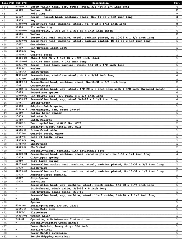
Refer to the part list for the location of the swaging machine parts mentioned below.
1 – Take out capscrew -1 and washer -9 to remove operating lever from square drive lug of crankshaft -36.
2 – Take out screws -26 and -27 and remove gear guard -28.
3 – Remove internal reversing latch, which consists of the following parts:
-29 Lift Pin, Reverse Latch
-46 Spring Latch
-47 Adapter, Latch Spring
-48 Hex Jam Nut 3/8 x 3/16
-49 Collar, Latch Spacer
-50 Bolt, Latch
-51 Latch, Reverse
(Note do not replace gear guard)
4 – The drive motor and reduction gear, already assembled are shipped mounted on a 12″ x 17 1/2″ x 1/2″ Steel base plate, shown in Figure B-1.
This plate is predrilled with the four mounting bolt holes for the Type II Swaging Machine.
Place the Swaging Machine on the base plate and using 3/8 x 1 1.4″ allen head bolts with flat washers secure the machine and the base plate to the bench.
5 – Slide the smaller sprocket onto the output shaft of the speed reducer, but do not secure it.
6 – Engage the roller chain with the two sprockets and then engage the larger sprocket with the square drive lug of the swaging machine. Secure it with capscrew -1 and flat washer -9.
7 – Slide the smaller sprocket in or out on the output shaft of the speed reducer to align it with the larger sprocket and then secure it with the setscrew in its hub.
8 – Adjust the spacing of the two sprockets to obtain proper chain tension. The chain can be tightened by transferring the flat washers on the mounting bolts of the reducer gear housing from the underside of the housing to the upper side. Transferring rather than simply removing the flat washers avoids the necessity of changing to a shorter mounting bolt. Be sure to transfer the same number of washers on each of the four mounting bolts.
A final fine adjustment can be obtained by loosening the mounting bolts of the Swaging Machine and sliding it on the base plate in the appropriate direction as permitted by its slotted mounting holes. The chain is properly tensioned when its slack permits a total crossways movement of the chain of 1/4″.
9 – Install the Chain Guard between the motor drive unit and the swaging machine and secure it to the base plate with two hex head machine screws engaging tapped holes provided in the base plate.
10 – Plug the electrical cord into a suitable electrical power supply (110 volt).


