B) 1.5 Horse Power Single Phase 115 Volt Motor, Type TEFC.
C) Right Angle Gear Reducer.
D) Foot Switch with 7.5 feet of cord connected to motor and 9 feet of cord for connection to power supply.
E) 2 Chain Sprockets, Roller Chain and Adjustable Base to tighten chain.
F) Chain Guard.
G) Steel base plate to which both the reduction gear housing and the swaging machine can be secured in their proper relative locations by cap screws.
Unless otherwise specified in the customer’s purchase order, power drive units will be shipped from the factory wired for 115 volts power supply and the 9 ft. 3-wire power supply cable will have a standard 3-prong plug (2 line and 1 ground) assembled to its free end.
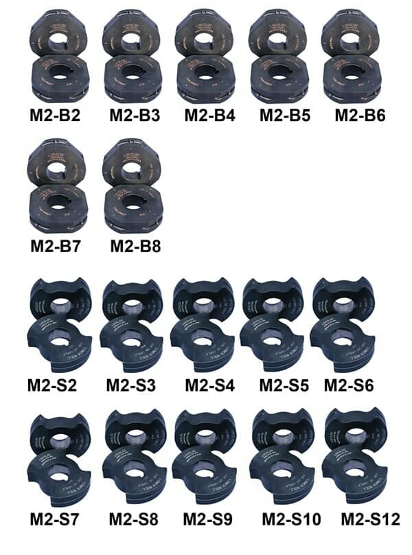
REPLACEABLE DIES – Sold Separately
Precaution
When swaging fittings on to 1 x 19 construction wire rope, remember that there is little or no compression remaining in this construction. The wire rope itself is very solid with little or no “give.”
A combination of a 1 x 19 construction wire rope manufactured on the “high side” of its tolerance and a fitting with a hole running on the “low side” of its tolerance (see dimensions to fittings under specifications) will exaggerate this problem. Remember a swaging machine must have room to “flow” or “move” the steel in the fitting to form around the wire rope. There must be space to accomplish this.
In addition, many manufacturers do not drill the hole in their fittings deep enough. This leaves a space at the base of the fitting of solid steel. This distance can vary from 1/4″ up to over 1″. The Locoloc® Kearney machine simply cannot perform the impossible and swage solid metal, again there must be room for the steel to “flow” or “move.”
When any of the situations above occur, the result can only be broken dies, sprung machines, ruined fittings and perhaps loss of expensive wire rope. The majority of cases could easily be avoided by checking the following before attempting to swage:
Diameter of wire rope – is it on high side of tolerance?
Inside diameter of fitting – will the wire rope fit with ease?
Depth of hole in fitting – do not attempt to swage over solid steel, begin swage at the bottom of the hole.
Hardness of steel – check Rockwell Hardness. See above.
Do not add leverage to your swaging machine by extending the handle beyond the length of the handle extension we supply. The handle is designed to accomplish the maximum compression for which the machine is designed. Adding to the handle length will result in broken dies, broken gears, and/or sprung frames and large repair costs.
Maintenance
Cleaning: Dust, dirt, or other foreign material should not be allowed to collect on the swaging machine; it will eventually work its way into the mechanism and cause excessive wear and damage.
Before installing a set of roll dies, wipe their actives surfaces carefully with a clean soft cloth to be sure not grit will mar the surfaces of the roll dies.
Stubborn accumulations of grease or other sticky material can usually be removed by wiping with a petroleum base solvent.
Lubrication: Each swaging machine is packed with lubricant when it is assembled at the factory, and no subsequent periodic lubrication is required. If and when the machine is disassembled for repair or overhaul, the old grease on the bearings and gear teeth should be cleaned out with solvent and these parts should be packed lightly with extreme-pressure low-temperature grease, MIL-G-7118 or equivalent.
Corrosion Protection: If the swaging machine is located in a dusty or humid environment, it is recommended that a hood of fairly heavy vinyl or canvas be used to cover it when it is no in use.
Contact of bare hands with the working surface of the roll dies must be avoided to prevent finger print corrosion.
Each time a set of roll dies is removed from the swaging machine, the roll dies and the exposed portions of the machine shafts should be lightly coated with a clean corrosion resistant oil.
Additional Info
Factory Installation: If so ordered, the Power Drive will be shipped from the factory assembled to the Type II Swaging Machine.
In this case, the assembly of the Type II Swaging Machine and the Power Drive is attached to and enclosed in the lower half of the shipping container/bench and the dies and accessories are secured in the upper half. Here again, upon receipt at the customer’s plant, the assembly of the Type II Swaging Machine and Power Drive is detached from the shipping container/ bench, transferred to the bench surface, and secured there by inserting the shipping bolts into predrilled holes in the bench.
WARRANTY RESTRICTION INFORMATION: Loos & Co. restricts the warranty on all Locoloc® Kearney machines to the use of only Locoloc® fittings to fully guarantee the performance of our machines. We cannot be responsible for machine damage caused by another manufacturer’s fittings that exceed Rockwell hardness of 62, A scale or RB100.
Obviously, there are certain fittings that will be swaged by Locoloc® Kearney machines that we do not or cannot supply. When this occurs we request that you check the hardness of the fittings to determine that the maximum Rockwell hardness is 62, A scale, again, we cannot be responsible for machine damage caused by another manufacturer’s fittings that exceed Rockwell hardness of 62, A scale or RB100.