M1 For The Straight Shank Terminal
M1 Roll Swaging Machine for Straight Shanks Video Transcript
Welcome back to Loos Tube
Today you’re gonna learn how to use our M1 LOCOLOC Swaging machine
This how-to video will demonstrate how to prepare and swage straight shank terminals
You should have already set up your LOCOLOC M1 swaging machine with the proper set of dies and the feed guide attached
For swaging straight shanks you will need a high quality cable cutter, a permanent marker, an attribute gauge, and your included instruction manual
Once your M1 is ready to swage, prepare the cable and fitting
Begin by cutting the cable cleanly and squarely to ensure that it will insert into the bore of the terminal
The fit will be snug so it is essential that the cable wires don’t spread or broom out
You will now need to identify the point on the fitting where you will begin the swage
Start by inserting the cable fully into the terminal and mark on the cable where it first appears at the end
This is referred to as point A in the manual
Place the cable beside the terminal aligning point A with the tip
Now mark on the fitting where the cable ends, this is point B
Now place the cable next to point B perpendicular to the fitting
And make another mark that’s equal to the diameter of the cable, this is point C
Point C is very important to find and remember
Because it is the point you will align with the dies to begin your swage
Press the cable partly back into the bore then sharply
Then insert the remainder of the way
This will ensure that the fitting will remain in place on the cable, while being inserted into the machine
Now ensure that the upper and lower dies are centered
There should be a clear opening to lay your fitting and cable into
Insert the end of the fitting into the feed guide adapter and snap the cable into place
Be sure that you can see your point C marking from earlier
Also keep in mind that the length of cable needs to be supported
If there’s too much slack in the cable, the resulting swage may not be straight
Now grasp the pins on the lower die and turn counter clockwise making sure to align the points of the dies on point c
If you begin the swage at any point above point c, you risk significant damage to your tool that may result in costly repairs
You can now begin the swage
Pump the handles until one full pass has been made
Now rotate the terminal within the feed guide 90 degrees and snap back into place
As before, turn the dies counter clockwise until the points meet again at your C mark
Make a second pass
Rotate the terminal again this time 45 degrees and snap into place
Then turn the dies to meet at point c and make one final pass
Never use more than four passes as it may cause work hardening
If more than four passes are required to meet the after swage diameter, your tool may need to be repaired
Your LOCOLOC terminal is now ready to use
Test the diameter of the shank to ensure a proper swage was achieved
If it passes through, your swaged fitting will maintain the break strength of the cable
Thank you for watching Loos Tube
Be sure to subscribe below for updated content and with any questions visit our website or contact our customer service number department
SETTING UP THE MACHINE
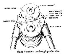
Select from the kit the matched pair of roll dies suited for the size cable onto which you are preparing to swage a terminal. Each roll die has the nominal cable size for which it is suited stamped on the flat sides. Install the roll die marked “UPPER” on the top shaft of the machine so that the word “UPPER” stamped on one flat side of the roll die is visible. Install the other roll die of the matched pair, marked “LOWER” on the bottom shaft of the machine so that the word “LOWER” stamped on the flat side of the roll die is visible and the two pins protruding from that face are on the outside. When the keys in the shaft engage the keyways in the roll die, the rolls are properly indexed with one another. Push the rolls all the way onto the shafts by hand and secure them with the special flat washer and cap screws, as shown in Figura 1.
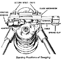
Insert the proper size feed guide adapter in the feed guide assembly. The two feed guide adapters in the kit are marked with the range of cable size with which each should be used. Secure the adapter with the spring wire keeper shown at the extreme left hand end of the feed guide assembly in Figure 2. Attach the feed guide assembly to the machine with the two allen head caps, as shown in Figure 2. The machine is now ready to receive and swage the cable-terminal assembly.
Preparing The Cable And Terminal
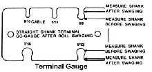
It is essential that the cable and the terminal you selected to swage onto it are both of the proper size. Check the cable diameter with a micrometer and, using the gauge included in the kit, Figure 3, check the outside diameter of the terminal shank to be sure it corresponds to the size of the cable.
The cable is a fairly close fit in the bore of the terminal before swaging. It is important that the end of the cable be cut cleanly and squarely and that individual wires be prevented from brooming out. If necessary, recut the cable to obtain a good end. LOOS & CO. offers a full line of FELCO cable cutters which perform the operation excellently. Ask for full information.
It is also important that the terminal and the cable be engaged over the full length of the terminal bore so that the full strength of the swaged joint will be realized. Probe the bore of the terminal with a stiff wire to make sure that the depth of the bore is as specified in the Military Specification Sheet for that particular terminal and that the bore is not plugged by dirt, chips or other foreign objects.
Figure 4-7 apply only to Eye and Stud Terminals

Push the cable into the fitting until the end of the cable reaches the bottom of the bore. Mark the cable at point (A), as shown in Figure 4.

Place the cable beside the fitting shank and have mark (A) placed flush with the bottom of the shank. Mark the shank at point (B) using the end of the cable, as shown in Figure 5.

Place the cable next to the mark (B) and mark the shank at point (C), as shown in Figure 6.

Push the cable back into the fitting until mark (A) is flush with the bottom of the shank again. Start your swaging at mark (C) on the shank. as shown in Figure 7.
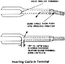
Insert the cable to approximately half the depth of the bore and, taking hold of the cable close to the end of the terminal, bend it sharply enough to set a bend into the cable, as shown in Figure 8. This is to ensure that the terminal will not move on the cable while they are being inserted in the swaging machine. On Fork Shank Terminals sizes 1/16 to 3/16, push the cable into the terminal until the end of the cable reaches the end of the bore. Pull the cable back 1/8″ to 1/4″short of the end of the bore, as shown in Figure 8. The cable-terminal assembly is now ready to be swaged.
SWAGING
Grasp the two pins protruding from the face of the lower roll in the machine and rotate the roll until the cutaway portions of the two rolls are centered opposite one another, providing a space to insert the cable-terminal assembly between the rolls. Place the cable terminal assembly in the feed guide with the free end of the terminal resting against the feed guide adapter. Slide the feed guide assembly to the right as far as it will go and then, by hand, rotate the lower roll counterclockwise until the two rolls meet in contact with the terminal one cable diameter away from its head, as shown in Figure 2.

Operate the handles of the swager in a ratcheting manner until the rolls have passed completely over the terminal sleeve. When the first pass has been completed a longitudinal fin or flash on two diametrically opposite sides will be noticeable on the swaged portion of the shank, as shown in Figure 9.

To eliminate longitudinal fin rotate the terminal 90 degrees from the first position and pass it through the rolls as outlined in preceding instructions. After the second pass, the terminal shank will appear smooth and round, as shown in Figure 10.
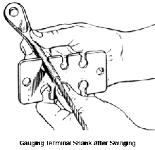
Measure the diameter of the terminal shank with the gauge, as shown in Figure 11. The shank should now slide through the slot from one end of the swaged portion of the other except for the slight flash which will be left after the second pass. The diameter over flash should not exceed the shank diameter after swaging by more than 0.010 inch. The gauge is made to pass a terminal which has been reduced to the proper diameter as specified in applicable MS drawings except over flash. If the terminal has not been sufficiently reduced, an additional pass may be necessary to reduce it to the required diameter. Rotate the terminal 45 degrees for the 3rd pass to make the terminal more uniformed.


