

Cable splicing is much easier if the cable is cut clean without frayed ends. We highly recommend No. C7, C9, C12 or C16 cable cutters as shown in the Loos & Co. Cableware® Division catalog.
LOCOLOC® Oval and Stop sleeves in a complete range of sizes are available through Loos & Co., Cableware® Division. Sleeves elongate after compression. To assure maximum holding allow the end of the cable to extend beyond the sleeve after it is compressed (see Figure 3). Keep the jaws of the swager at right angles to the sleeve being compressed, making sure the sleeve is aligned in the jaw grooves. Then close the swager jaws completely. (Note: for lap splices, at least two oval sleeves should be used.) Each Loos & Co. LOCOLOC® Swager is designed to work with one or more specific size sleeves. FOR USE ON ALL METAL CONSTRUCTION CABLES, 7×7, 7×19, 6×19 IWRC ON SIZES UP TO 3/16. You will not obtain optimum performance if you do not use the proper swager and sleeve combination. All compressions must be gauged to assure maximum holding strength, and it is recommended that all assemblies should be proof tested.
SWAGER OPERATION INSTRUCTIONS: #1P AIR-OPERATED SWAGING MACHINE
Place sleeve to be compressed in proper size groove in swaging tool. The cavity should match cable size to be swaged. A length of cable equal to the cable diameter should extend beyond the length of sleeve to achieve maximum holding. (See arrow in figure 3). After each swage turn sleeve 180° and swage the next one. To keep swaged sleeve straight.

Keep jaws of swaging tool at right angles to the sleeve to be compressed, making sure the sleeve is aligned in the jaw grooves. Close the swager jaws completely.
Finished sleeve should look like this. Be sure sleeves have been compressed the proper number of times. (See NUMBER OF COMPRESSIONS table)
Use Swaging gauge provided with the tool to check proper after swage diameter. Compressed sleeve should slide freely into size slot of gauge.
ADJUSTING INSTRUCTIONS: #1P AIR-OPERATED SWAGING MACHINE
(140 PSI Max Air Pressure)
- Loosen set screw (A) and (B), both sides, and cam wheel nut (C).
- Insert pin (such as 1/8″ drill bit in hole in front of adjusting wheel cam (D) and raise pin for more tension, lower for less tension (more tension makes a tighter swage).
- To properly adjust the swaging machine use the gauge that is supplied with the machine. Select the slot in the gauge corresponding to the sleeve size being swaged. The swaged portion of the sleeve should pass into the gauge easily. If it does not, then adjust your swager machine as follows: 1,2.
- Tighten set screw (A) and (B) and, nut (C).
- Gauge after-swage dimension periodically, (daily) when machine is in continuous service.
- Your Loos & Co., Cableware® Division Swager has been designed to give you years of trouble free service. To obtain the best possible performance, we recommend: (1) clean and lubricate all moving parts occasionally; (2) keep all bolts tight; (3) keep your swager properly adjusted using the simple procedures in 1,2,3.
- Disassemble jaw periodically and fill grease cavities on inner side of jaw.
- Put oil “20 wt.” into air connection on foot switch periodically as you would normal air tool.
CAUTION: DO NOT OVER TIGHTEN AS THIS WILL CAUSE EXCESS WEAR & OR BREAK THE JAWS OR OTHER DAMAGE!
| NUMBER OF COMPRESSIONS | ||
|---|---|---|
| Cable Diameter | Aluminum & Copper | |
| Mangas ovaladas | Manguitos Stop | |
| 1/16" | 2 | 1 |
| 3/32" | 2 | 2 |
| 1/8" | 3 | 2 |
| 5/32" | 3 | 2 |
| 3/16" | 4 | 2 |
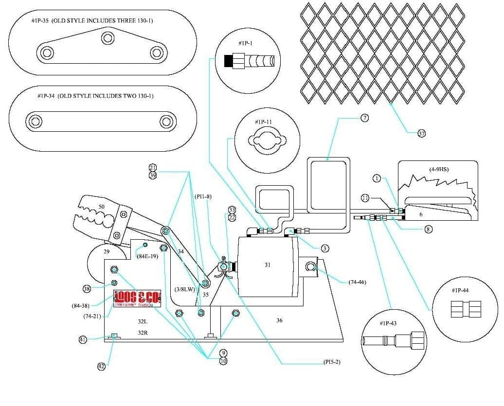
| Pieza# | Descripción | Cant. |
|---|---|---|
| #1P-1 | Acoplamiento, 3/16" ID X 1/8" MPT, #220B | 4 |
| #1P-3 | Codo, Calle, Acoplamiento, 1165A | 2 |
| #1P-6 | Interruptor de pedal | 1 |
| #1P-7 | Manguera, 3/16", baja presión, 60" | 2 |
| #1P-8 | Boquilla, 2", Dynaquip 117A2 | 1 |
| #1P-9 | Tuerca, 3/8-24, bloqueo UNRF | 4 |
| #1P-10 | Tornillo, 3/8-24, UNRF 1 3/8", cabeza hexagonal | 4 |
| #1P-11 | Abrazadera 7/16", O, Oetaker, 2 puntas | 4 |
| PI5-2 | Pasador de chaveta, SS, 3/32" Dia, 1 Pulgada | 1 |
| PI1-8 | Horquilla para piezas de 1/4" MS 3/8" Dia | 1 |
| #1P-50 | Conjunto de mordazas, para #1-P, Cabezal de máquina | 1 |
| #1P-21 | Tuerca, 5/8-18, hexagonal, de bloqueo, grado 8 | 3 |
| 84-38 | Nombre de la placa | 1 |
| 74-21 | Tornillo, No. 4 X 3/16" LG, Drive, SS | 2 |
| #1P-29 | Rueda, Ajuste | 1 |
| #1P-31 | Cilindro, Aire, Fabco | 1 |
| #1P-32R | Base, 2 piezas, lado derecho (incluye (1) 130-1) | 1 |
| #1P-32L | Base, 2 Piezas, L,H. Lateral (Incluye (1) 130-1) | 1 |
| #1P-33 | Conector, varilla roscada 1/2-20 (incluye #1P-22) | 1 |
| #1P-34 | Eslabón, superior (incluye (2) 130-1 Old Style) | 2 |
| #1P-35 | Eslabón, inferior (incluye (3) 130-1 Old Style) | 1 |
| #1P-36 | Marco, extensión | 1 |
| #1P-37 | Protector, 1/2", #16 Plano, 7" X 23" LWO, EXP Metal | 1 |
| #1P-38 | Tornillo, 7/16-14 X 3/8", juego largo | 2 |
| #1P-39 | Perno, 3/8" X 1", hombro del zócalo | 3 |
| #1P-41 | Tornillo, 1/4-20 X 3/8", cabeza hueca | 4 |
| #1P-42 | Arandela, 1/4", Estándar, Acero | 4 |
| #1P-43 | Tapón, 1/8 N.P.T. #726 Milton | 1 |
| #1P-44 | Acoplamiento, 1/8 N.P.T. | 1 |
| #4-9HS | Protección, interruptor de pedal, 522B14 | 1 |
| GA-1P | Indicador | 1 |
| 84E-19 | Tornillo prisionero, 1/4-20 X 1/4" cabeza hueca | 2 |
| 74-46 | Arandela, espaciador | 2 |
| 130-1 | Casquillo (9- Old Style /2- New Style Machine) | 9 |
| 3/8LW | Arandela,3/8" Bloqueo | 3 |